
Creating a Test Plan - FCC 234G
The FCC 234G option is used for FCC / IC (ISED) certification testing of cellular products (2G GSM / 3G WCDMA / 4G LTE). When creating a test plan, select the Type (technology) first; the form will show the corresponding options for the selected technology. Each technology is described separately below.
GSM
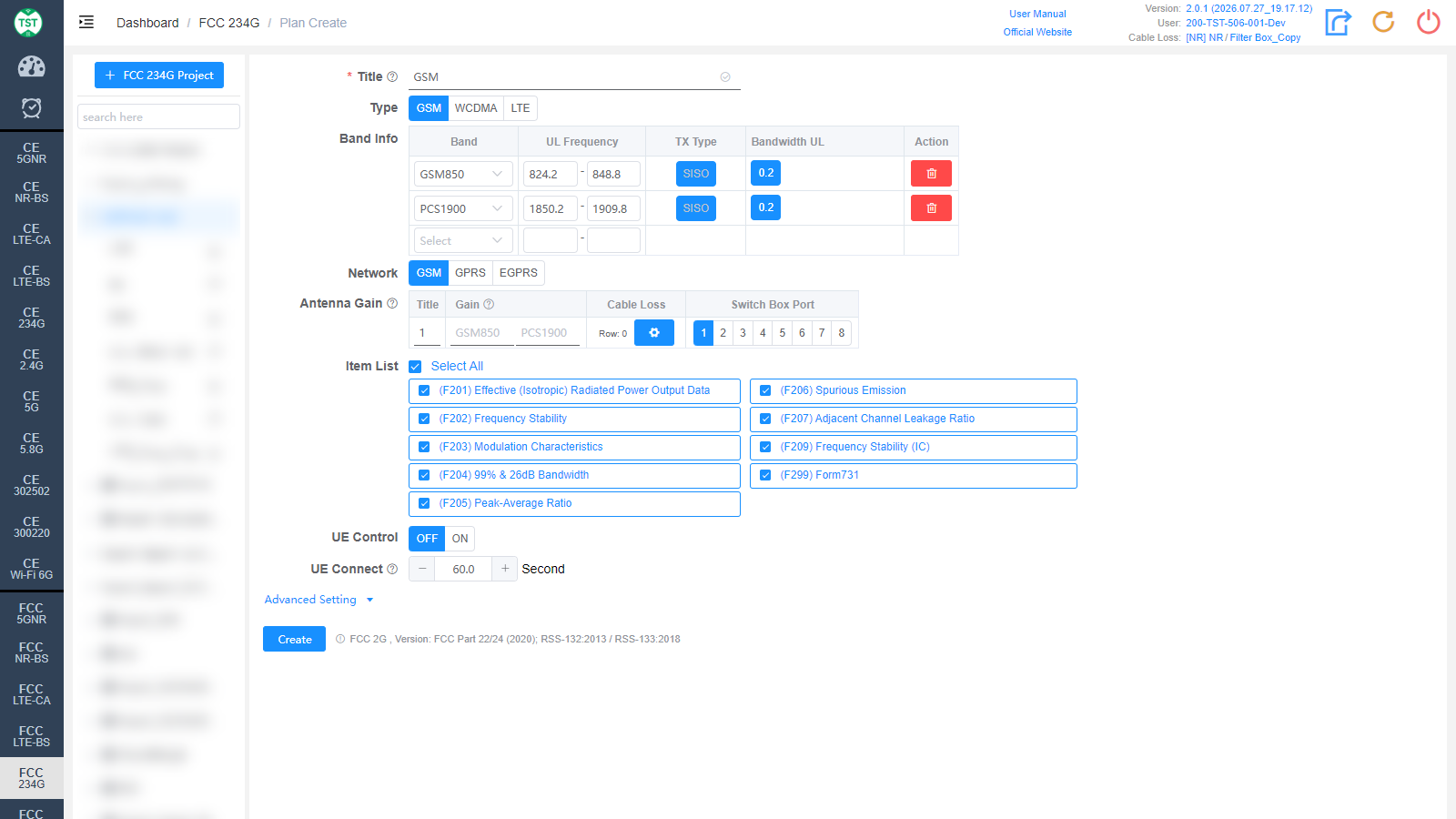
Title: Test plan name, entered by the user, e.g., GSM / B2 / LTE-Ant1.
Type: Technical category, select GSM here.
Band Info: Operating bands supported by the product, one band per row:
Band: Band name; GSM850 / PCS1900 are available for North American GSM. After selecting from the drop-down, the system automatically fills in the corresponding uplink frequency.
UL Frequency: Uplink frequency range (MHz) of the band, filled in automatically and editable.
TX Type: Transmission type, fixed to SISO.
Bandwidth UL: Uplink channel bandwidth, fixed to 0.2 (200 kHz) for GSM.
Action: Click the red delete icon to remove a band row; select a band from the bottom Select drop-down to add a new row.
Network: Network modes supported by the product, multi-select: GSM / GPRS / EGPRS. Select according to the product's actual support.
Antenna Gain: Antenna gain and cable loss configuration:
Title: Antenna number, named sequentially by default as 1, 2, 3, 4..., or manually input other names according to customer requirements.
Gain: Gain (dBi) of each antenna in the corresponding band. Generally 0 for products with built-in antennas such as phones and tablets.
Cable Loss: Cable loss of the RF cable from the product's antenna port to the Switch Box or the spectrum analyzer. How to Create Common Cable Loss.
Switch Box Port: Port number of the switch connected to the product's antenna, e.g., Ant1 connected to port 1, Ant2 connected to port 2.
Row: Click the number to change the number of antenna rows (i.e., the number of antennas); click the gear icon to manage cable loss details.
Item List: Test items included in GSM (FCC 2G), all selected by default:
(F201) Effective (Isotropic) Radiated Power Output Data
(F202) Frequency Stability
(F203) Modulation Characteristics
(F204) 99% & 26dB Bandwidth
(F205) Peak-Average Ratio
(F206) Spurious Emission
(F207) Adjacent Channel Leakage Ratio
(F209) Frequency Stability (IC, Canada)
(F299) Form731 — FCC Form 731 report
Note: In some standards, test parameters are mutually referenced between items. If only some items are checked, the test may not be able to proceed. It is recommended to create the test plan with the default items.
UE Control: Whether the software automatically controls the sample, default OFF. When OFF, the sample state (e.g., reboot, airplane mode) must be controlled manually during the test.
UE Connect: UE connection waiting time (seconds), default 60. That is, the timeout for the UE to connect to the base station emulator or to start up.
WCDMA
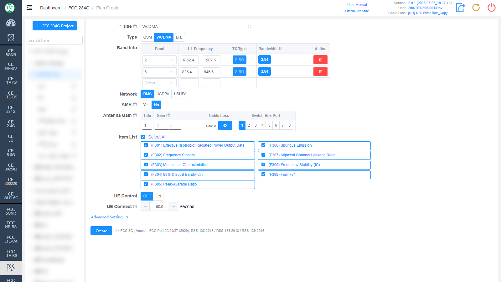
Type: Technical category, select WCDMA here.
Band Info: WCDMA bands supported by the product, e.g., Band 2 / 4 / 5. Bandwidth UL is fixed to 3.84 (WCDMA chip rate 3.84 Mcps); the other columns are the same as GSM.
Network: Network modes supported by the product, multi-select: RMC / HSDPA / HSUPA.
AMR: Whether the product supports AMR (Adaptive Multi-rate) voice, default No. AMR is for voice connections. This option appears after a Network is selected.
Item List: Test items included in WCDMA (FCC 3G), all selected by default:
(F301) Effective (Isotropic) Radiated Power Output Data
(F302) Frequency Stability
(F303) Modulation Characteristics
(F304) 99% & 26dB Bandwidth
(F305) Peak-Average Ratio
(F306) Spurious Emission
(F307) Adjacent Channel Leakage Ratio
(F309) Frequency Stability (IC, Canada)
(F399) Form731 — FCC Form 731 report
Title / Antenna Gain / UE Control / UE Connect are the same as GSM and are not repeated here.
LTE
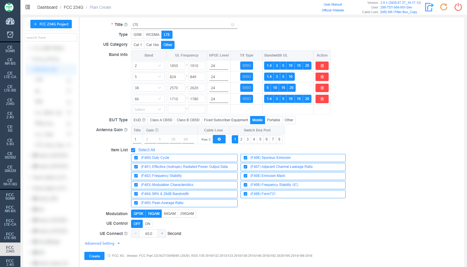
Type: Technical category, select LTE here.
UE Category: LTE category of the UE (user equipment), default Other:
Cat 1: LTE Category 1, low data rate IoT category.
Cat 1bis: Category 1bis, single-antenna variant with only one receive antenna, common in IoT modules.
Other: Other categories, for devices other than Cat 1 / Cat 1bis.
Band Info: LTE bands supported by the product, with an additional HPUE Level column compared to GSM / WCDMA:
Band: LTE band number, e.g., Band 2 / 5 / 38 / 66. Some bands have EUT Type restrictions which are annotated directly in the drop-down list, e.g., Band 5 is annotated "EUT Type: FCC: Other; IC: Mobile, Portable".
UL Frequency: Uplink frequency range (MHz), filled in automatically.
HPUE Level: Power class (dBm) of High Power UE, default 24. If the product does not support HPUE, keep the default value.
TX Type: Transmission type, fixed to SISO.
Bandwidth UL: Uplink channel bandwidths (MHz) supported by the band, multi-select, e.g., 1.4 / 3 / 5 / 10 / 15 / 20. Available options vary by band; select according to the product's actual support.
EUT Type: Type of the equipment under test, which affects the applicable regulations and limits:
EUD: End User Device.
Class A CBSD / Class B CBSD: Class A / Class B Citizens Broadband Radio Service Device (CBRS, applicable to Band 48, etc.).
Fixed Subscriber Equipment: Fixed subscriber equipment.
Mobile: Mobile device.
Portable: Portable device.
Other: Other types.
Item List: Test items included in LTE (FCC 4G), all selected by default:
(F400) Duty Cycle
(F401) Effective (Isotropic) Radiated Power Output Data
(F402) Frequency Stability
(F403) Modulation Characteristics
(F404) 99% & 26dB Bandwidth
(F405) Peak-Average Ratio
(F406) Spurious Emission
(F407) Adjacent Channel Leakage Ratio
(F408) Emission Mask
(F409) Frequency Stability (IC, Canada)
(F499) Form731 — FCC Form 731 report
Modulation: Modulations supported by the product, multi-select: QPSK / 16QAM / 64QAM / 256QAM, QPSK + 16QAM selected by default. Select according to the modulations actually supported in the product specification.
Title / Antenna Gain / UE Control / UE Connect are the same as GSM and are not repeated here.
Advanced Setting
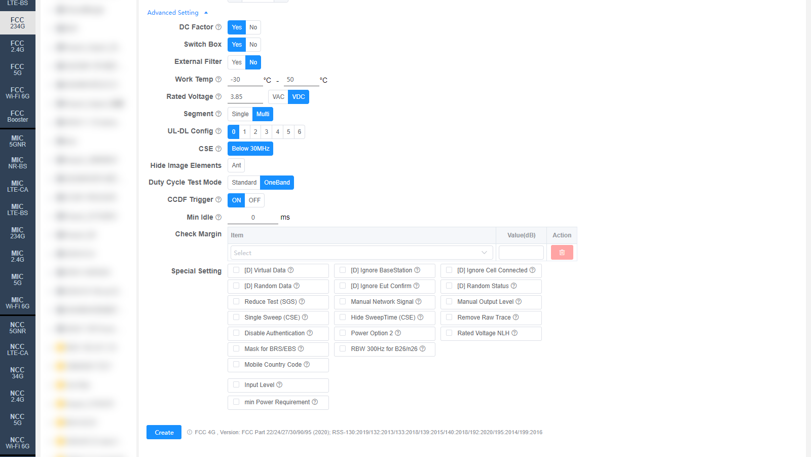
All settings in Advanced Setting can generally be kept at their default values. Adjust them only when the test results are abnormal or there are special test requirements. The figure above takes LTE as an example; GSM / WCDMA fields differ slightly, and the differences are marked below.
DC Factor (GSM / LTE): Whether to enable duty cycle factor correction, default Yes. Used for spurious emission tests (applicable to GSM or LTE TDD).
Switch Box: Whether to use a Switch Box (RF switch), default Yes. If a Switch Box has not been purchased, select No, and the product will be directly connected to the spectrum analyzer for testing.
External Filter: Whether an external filter is used in the RF path during testing, default No.
Work Temp: Normal operating temperature range (°C) of the product, default -30 ~ 50. Affects the frequency stability test.
Rated Voltage: Rated operating voltage of the product, default 3.85 VDC, selectable VAC (AC) or VDC (DC). Affects the frequency stability test.
PDP (GSM only): Whether to enable the PDP (Packet Data Protocol) Context, default No.
Uplink Slot (GSM only): Number of uplink slots, selectable 1 / 2 / 3 / 4, default 4. Used for the F205 Peak-Average Ratio test.
Segment (LTE only): Band segmentation mode, selectable Single / Multi, default Multi. Used for the F406 band edge test.
UL-DL Config (LTE only): LTE TDD uplink-downlink subframe configuration (0 ~ 6), default 0, corresponding to the TDD UL-DL configurations defined by 3GPP. Only relevant for TDD; it does not affect FDD products.
CSE: Conducted Spurious Emissions setting. Below 30MHz is enabled by default and additionally tests 9 kHz ~ 150 kHz / 150 kHz ~ 10 MHz / 10 MHz ~ 30 MHz. The default value can be changed on the Setting page.
Hide Image Elements: Select the elements to hide in report images (e.g., the Ant antenna marker).
Duty Cycle Test Mode: Duty cycle test mode, selectable Standard or OneBand (single-band fast mode), default OneBand.
CCDF Trigger: CCDF (Complementary Cumulative Distribution Function) trigger mode, default ON. If ON is selected and the device is an R&S signal and spectrum analyzer, please ensure proper wiring; the default value can be changed on the Setting page.
Min Idle: Minimum idle time (ms) for the duty cycle test, default 0.
Check Margin: Test margin check. Select an Item and fill in Value(dB); when the margin between the test result and the limit is smaller than the set value, the system will flag it.
Special Setting: Special settings. Options prefixed with [D] are debug options and do not need to be checked for normal testing:
[D] Virtual Data: The system will use virtual data.
[D] Ignore BaseStation: The system will ignore the base station.
[D] Ignore Cell Connected: The system will ignore the cell connected state.
[D] Random Data: The system will use random data.
[D] Ignore Eut Confirm: The system will ignore the EUT confirmation.
[D] Random Status: The system will use random status.
Reduce Test (SGS): Reduced testing (SGS Lite V1).
Manual Network Signal: Set the Network Signal manually; the system will not set it for the base station.
Manual Output Level: Set the Output Level manually; the system will not set it for the base station.
Single Sweep (CSE): CSE uses single sweep. Modifying this option requires a retest to take effect (ReTest).
Hide SweepTime (CSE): Hide the sweep time of CSE. Modifying this option requires a recalculation to take effect (ReCalc).
Remove Raw Trace: For F406, remove the raw trace and hide RBW/VBW in the report.
Disable Authentication: Disable authentication during the attach procedure.
Power Option 2: Use Option 2 for CBSD band power tests.
Rated Voltage NLH: Display NV, LV, HV for F402 / F409 tests when the rated voltage is not specified.
Mask for BRS/EBS: Emission mask replaces the band edge test for Band 7 / 38 / 41.
RBW 300Hz for B26/n26: Refer to KDB 971168 D02 Section VIII (c), Part 90 (814-824 MHz).
Mobile Country Code: MCC (Mobile Country Code), range 0-999, default 1. Applicable to Anritsu MT8000 / MT8821.
Input Level: Input level (dBm).
min Power Requirement: Minimum power requirement, default 0 dBm.
Referenced regulations (displayed next to the Create button according to the selected Type):
- FCC 2G (GSM): FCC Part 22/24 (2020); RSS-132:2013 / RSS-133:2018
- FCC 3G (WCDMA): FCC Part 22/24/27 (2020); RSS-132:2013 / RSS-133:2018 / RSS-139:2015
- FCC 4G (LTE): FCC Part 22/24/27/30/90/95 (2020); RSS-130:2019 / 132:2013 / 133:2018 / 139:2015 / 140:2018 / 192:2020 / 195:2014 / 199:2016